Pre-flight Checklist
- Review the full guide: Read all sections before starting to understand the overall assembly flow.
- Check the Bill of Materials (BOM): Ensure you have all parts listed in the BOM section.
- Prepare your workspace: Set up a clean, well-lit area with enough space for assembly.
- Gather your tools: Have all required tools ready. See tool lists in each section.
- Download 3D Parts: Download the complete set of 3D-printable parts from
assets/3d_parts.zip: Download 3d_parts.zip. All required.stlfiles are listed in the 3D Parts Library. - Download Electronics Files (Optional): For users who wish to check the electronics design in KiCad, the KiCad design files are available in a single archive at
assets/kicad_elec_parts.zip. Download kicad_elec_parts.zip.
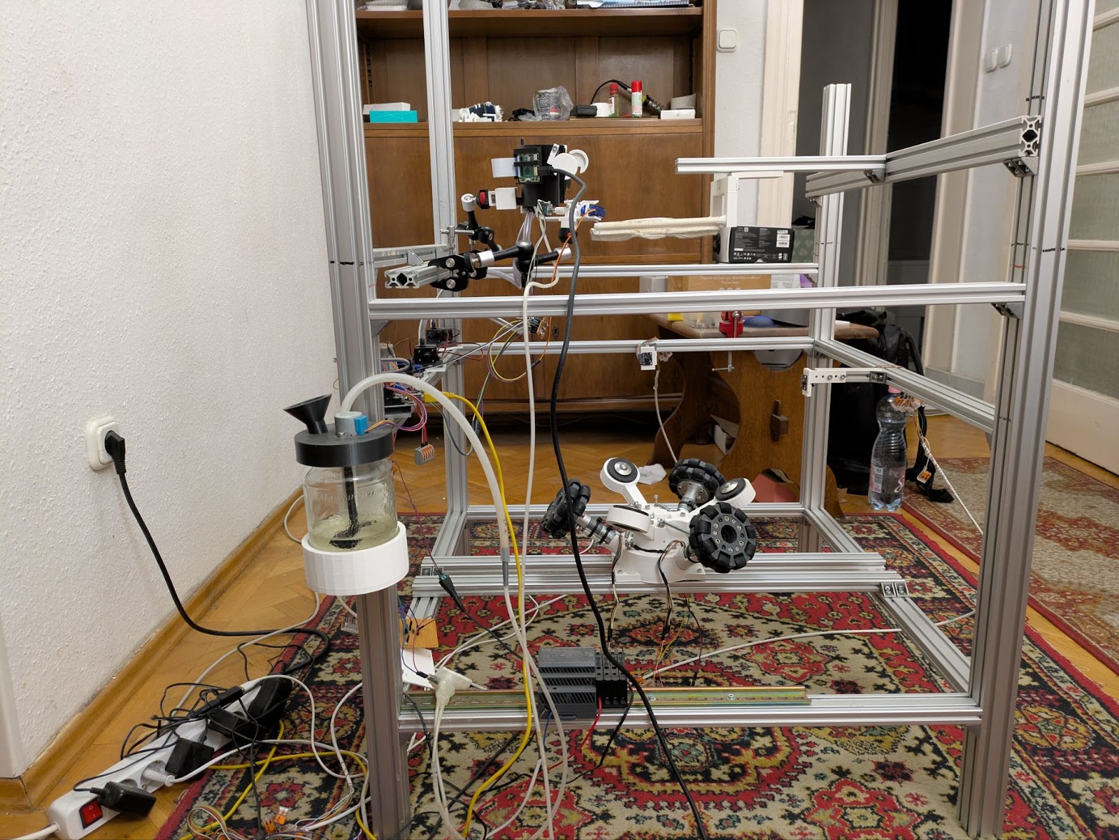
1. Frame Assembly
The frame provides a rigid, modular structure for all components. It is built from standard aluminum profiles, allowing for easy adjustment.
Required Parts
- Aluminum Profile, 40x40mm (4 x 100cm for pillars)
- Aluminum Profile, 40x20mm (10 x 70cm for crossbeams)
- M4x8 Screws[m4-8-screw]
- M4 T-slot Nuts[m4-tslot-nut]
Tools
- Hex key set (for M4 screws)
- Tape measure
- Metal file (to deburr cut profile ends)
Instructions
- Cut Profiles: Cut aluminum profiles to the lengths specified in the cut list below. Ensure cuts are straight and deburred.
- Assemble Base: Construct the bottom level using four 70cm crossbeams and connect them to the four 100cm pillars at the base.
- Assemble Middle Level: Attach crossbeams to create the middle level, which will hold the sensors and reward system.
- Assemble Top Level: Add the final crossbeams for the top level, which supports the VR headset and harness.
- Check for Squareness: Ensure the frame is square and all connections are tight.
Frame Cut List
- Pillars: 4 × 100cm (40x40mm)
- Crossbeams: 10 × 70cm (40x20mm)
- Motor Mounts: 2 × 80cm (40x20mm)
- Sensor Mounts: 2 × 10cm (20x20mm)
- VR Mount: 1 × 60cm (40x20mm)
- Harness Mounts: 1 × 80cm (40x20mm), 1 × 30cm (40x20mm)
Refer to the 3D Parts Library for all frame-related printable parts.
QA Checks
- The assembled frame is stable and does not wobble.
- All profile ends are smooth and free of sharp edges.
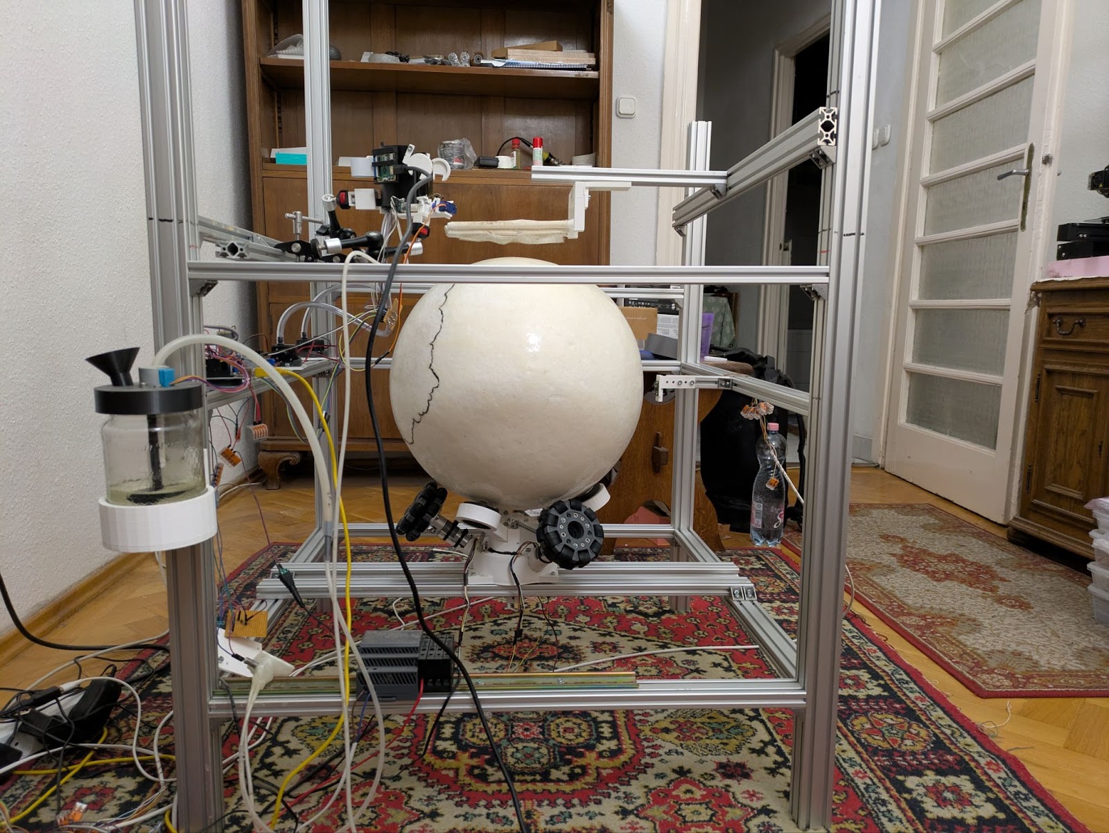
2. Locomotion System
The locomotion system allows the rat to move in the virtual world. It consists of a large styrofoam ball that rests on three omni-directional wheels, each driven by a motor.
Required Parts
- 3x Pololu 99:1 25D Motor[pololu-motor]
- 3x 100mm Omni-directional Wheel[omniwheel]
- 3x 8mm Universal Mounting Hub[mounting-hub]
- 1x 40cm Styrofoam Ball[styrofoam-ball]
- 1x Flex Seal (Clear)[flex-seal]
- 2x L298N Motor Driver[l298n-driver]
- 1x HDR-100-12N Power Supply[psu-12v]
- 3x 4mm to 8mm Set Screw Shaft Coupler[shaft-coupler] (Note: This is a custom part, see BOM for details)
Tools
- Soldering iron and solder
- Wire stripper and cutter
- Screwdriver set
Instructions
-
Prepare Ball: This is an essential step to ensure the ball is durable and functions correctly. The raw styrofoam is easily damaged by the rat's claws and does not provide good traction. Coating it creates a tough, smooth surface that rolls much better on the bearings.
Coating Process
- First Coat: Place the ball on a stand. Pour the Flex Seal Liquid on top and use a brush to smooth it out into a single, even layer covering most of the ball.
- Drying: Let the ball dry for at least 24 hours. The bottom part will not be covered at this stage.
- Second Coat: Once dry, mark the uncovered area with a marker. Carefully paint the remaining part with a brush, avoiding a thick overflow onto the already-covered areas.
- Final Curing: Allow the ball to cure for another 24 hours before assembly.
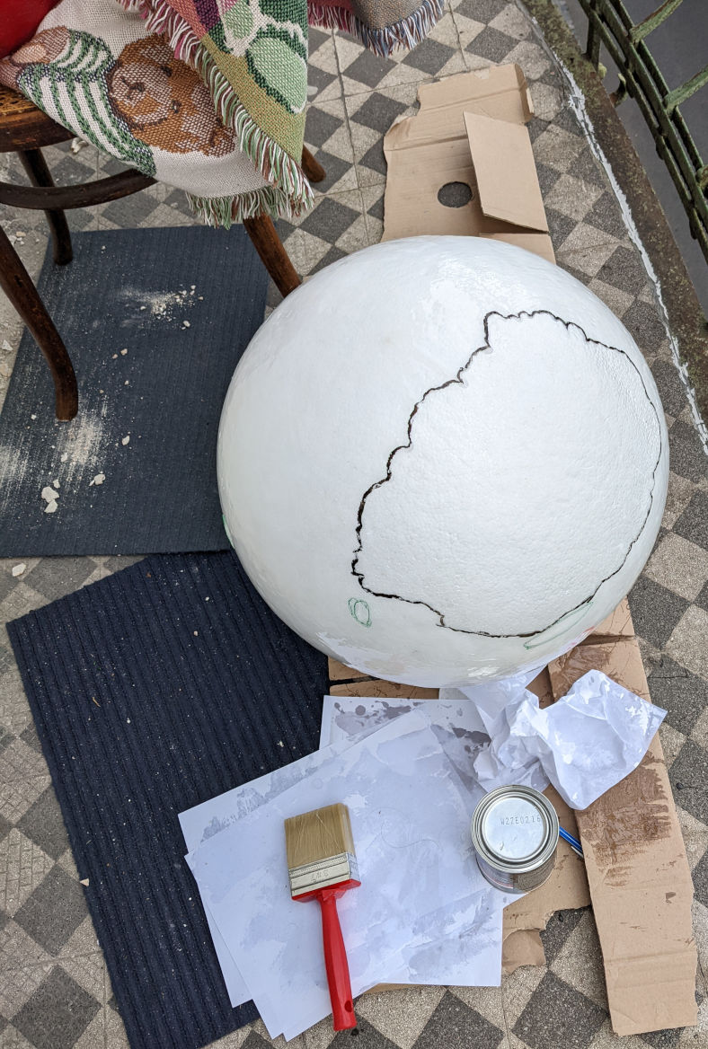
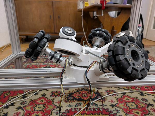
Applying the Flex Seal Liquid coating to the ball. This step is essential. - Mount Motors: Attach the three Pololu motors[pololu-motor] to the 3D-printed locomotion base.
- Attach Hubs and Wheels: Secure the mounting hubs[mounting-hub] to the motor shafts. Then, mount the omni-wheels[omniwheel] to the hubs.
- Assemble Base: Follow the `spawn_base_ver3_18a.blend` file to assemble the 3D-printed base parts.
- Install in Frame: Mount the entire locomotion assembly onto the bottom level of the main frame.
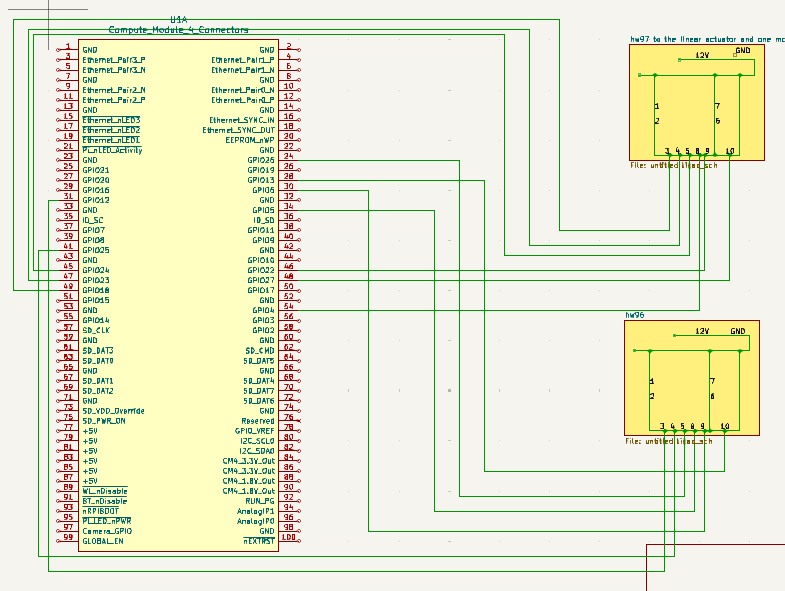
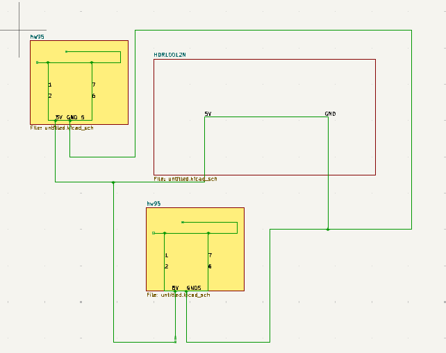
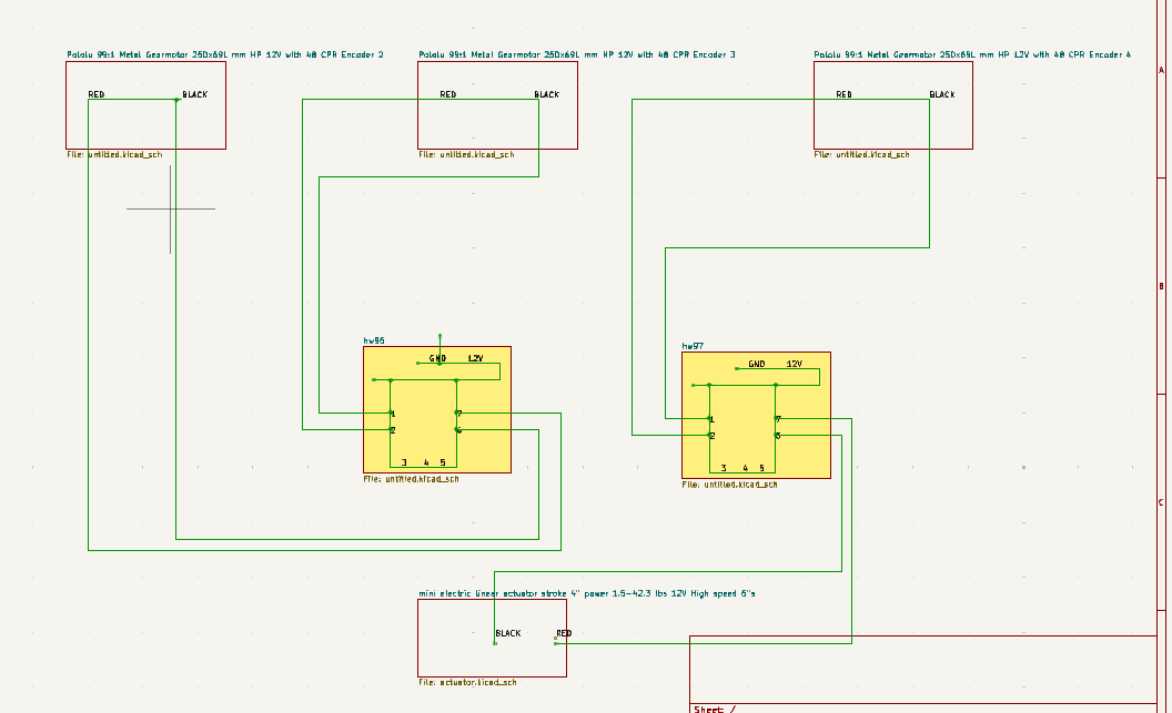
- Wire Electronics: Connect the motors and their encoders to the L298N drivers[l298n-driver]. Connect the drivers to the Raspberry Pi and the 12V power supply[psu-12v] according to the KiCad diagrams.
- Place Ball: Gently place the coated styrofoam ball on top of the three omni-wheels.
Refer to the 3D Parts Library for all locomotion system printable parts.
3D Model: Stand/Ball
QA Checks
- The ball spins freely in all directions when moved by hand.
- Motors run smoothly when powered, turning the ball as expected.
- Encoder signals are correctly read by the Raspberry Pi.
3. Ball Sensors
Two optical flow sensors track the ball's movement, providing the data needed to control the game.
Required Parts
- 2x PAA5100JE Optical Sensor[paa5100je-sensor]
- 3D-printed sensor mounts
Tools
- Screwdriver
Instructions
- Print Mounts: 3D print the sensor mounts using `motion_sensor_mount.blend`.
- Install Sensors: Secure the PAA5100JE sensors[paa5100je-sensor] into the printed mounts.
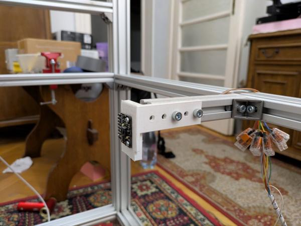
- Mount on Frame: Attach the mounts to the middle frame level. Position them 90 degrees apart, facing the ball.
- Set Distance: Adjust the mounts so the sensors are at the optimal distance from the ball's surface for reliable tracking.
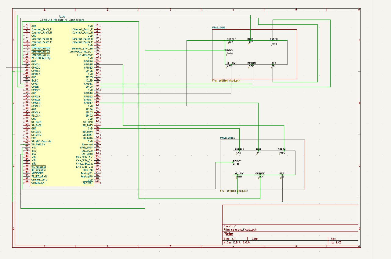
- Wire to Pi: Connect the sensors to the Raspberry Pi according to the `sensors` KiCad diagram.
Refer to the 3D Parts Library for the sensor mount.
QA Checks
- Sensors have a clear, unobstructed line-of-sight to the ball.
- Mounts are rigid and do not vibrate during operation.
- The system correctly reports ball movement when you spin it by hand.
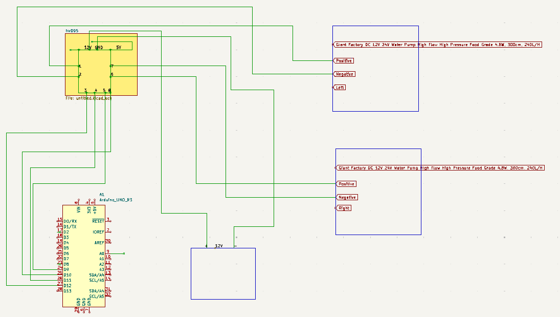
4. Reward Circuit Installation
The reward circuit delivers sugar water for correct actions and an air puff for negative feedback.
Required Parts
- 2x Mini Air Pump (12V)[air-pump]
- 1x Grove Pressure Sensor (MPX5700AP)[pressure-sensor]
- 1x PVC Tubing (4/2mm & 10/6mm)[pvc-tubing]
- 1x T-junction (4mm)[t-junction]
- 1x SG90 Micro Servo[sg90-servo] (for mixer)
- 1x 12V Mini Solenoid Valve[solenoid-valve]
Tools
- Scissors or tube cutter
- Screwdriver
Instructions
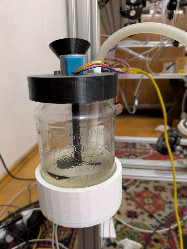
- Assemble Reservoir: 3D print the reservoir holder and mixer cap. Attach the SG90 servo[sg90-servo] to the cap to act as a mixer.
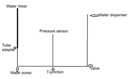
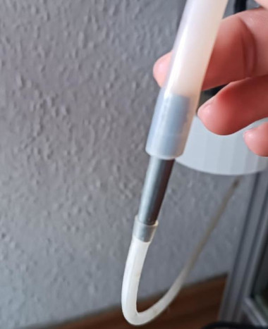
- Set up Water Line: Connect the 10/6mm PVC tubing[pvc-tubing] from the water reservoir to one of the pumps. Use a 3D-printed adapter to connect the 4/2mm tubing to the pump's outlet.
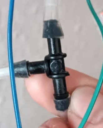
- Install Sensor and Valve: Insert a T-junction[t-junction] in the 4/2mm line. Connect one branch to the pressure sensor[pressure-sensor]. Install the solenoid valve downstream from the T-junction.
- Set up Air Puff System: Connect the second pump (blower)[air-pump] to tubing. Position the outlet near the headset to deliver a gentle air puff.
- Mount Components: Mount the entire assembly to the middle level of the frame. Run the final water delivery tube and air puff tube to the headset area.
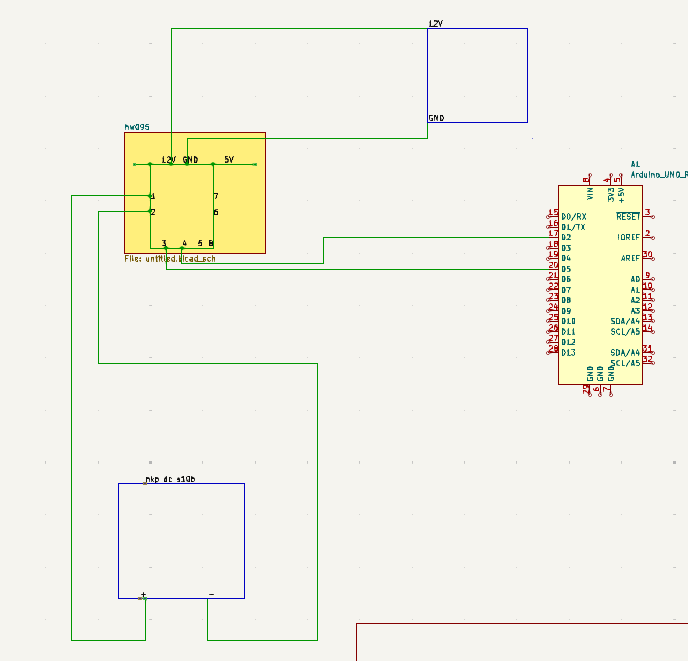
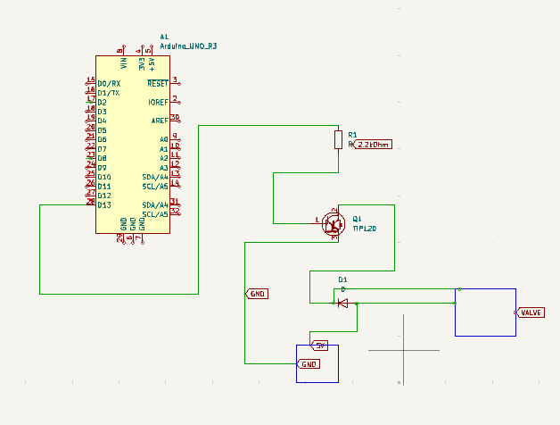
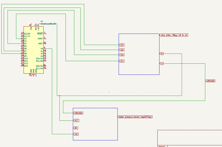
- Wire Electronics: Connect the pumps, sensor, valve, and servo to the control board as per the KiCad diagrams.
Refer to the 3D Parts Library for all reward circuit printable parts.
QA Checks
- The water line is free of leaks.
- The pressure sensor provides a stable reading.
- The solenoid valve opens and closes crisply on command, dispensing a single drop.
- The air puff is noticeable but not stressful for the animal.
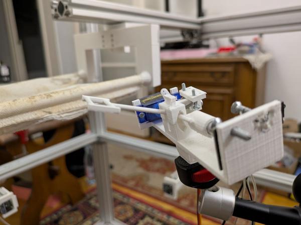
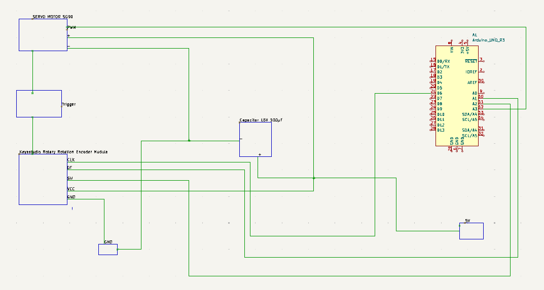
5. Trigger Mechanism
The trigger allows the rat to perform the 'shoot' action in the game by pulling a lever.
Required Parts
- 1x SG90 Micro Servo[sg90-servo]
- 1x Rotary Encoder (Keyestudio)[rotary-encoder]
- 2x Spring E0063-007-0380S[spring-e0063]
- 3D-printed housing and lever
Tools
- Small Phillips screwdriver
- Pliers
Instructions
- Print Parts: 3D print the lever, housing, and spring holder from `vr_headset6_rev15_lever3_a8.blend`.
- Install Components: Mount the rotary encoder and SG90 servo[sg90-servo] inside the housing.
- Assemble Lever: Place the lever into the housing, connecting it to the encoder and servo.
- Attach Springs: Attach the two springs[spring-e0063] to the lever and spring holder to provide return tension.
- Mount Assembly: Attach the trigger assembly to an adjustable arm on the frame. Position it within easy reach of the rat.
Refer to the 3D Parts Library for all trigger mechanism printable parts.
3D Model: Trigger
QA Checks
- The lever moves smoothly and returns to the neutral position.
- The encoder correctly registers lever movement.
- The servo can actuate the lever programmatically.
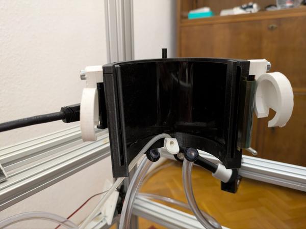
6. Display System
A curved display provides the rat with an immersive visual feed from the game.
Required Parts
- 1x OLED Display Module[oled-display]
- 3D-printed screen holder
Tools
- Screwdriver
Instructions
- Print Holder: 3D print the screen holder using `full_headset_guide.blend`.
- Mount Display: Carefully secure the OLED display[oled-display] into the holder.
- Attach to Frame: Mount the holder onto an adjustable arm on the top level of the frame.
- Position Screen: Adjust the arm to place the screen at the rat's eye level, ensuring a clear and panoramic field of view.
Refer to the 3D Parts Library for all display system printable parts.
3D Model: Headset
QA Checks
- The screen is securely mounted and stable.
- The display powers on and shows a clear image.
7. Rat Harness System
The harness safely suspends the rat above the ball, allowing its paws to rest on the surface while preventing it from leaving the apparatus.
Required Parts
- 3D-printed harness components
- Soft fabric or padding material
Tools
- Scissors
- Fabric glue
Instructions
- Print Harness: 3D print the harness components from `harness.blend`.
- Assemble and Pad: Assemble the printed parts and line the interior with soft fabric for the rat's comfort.
- Mount to Frame: Attach the harness to the top level of the frame.
- Adjust Height: Adjust the height so the rat is comfortably supported with its paws resting naturally on the ball. The rat should be able to move slightly vertically but not be able to climb out.
Refer to the 3D Parts Library for all harness printable parts.
QA Checks
- The harness is secure and can safely support the rat's weight.
- The rat can move the ball with its paws without significant restriction.
Final Verification
- Full System Check: Power on the entire system. Verify that all components (motors, sensors, display, etc.) are recognized by the software.
- Manual Control Test: Use the control software to manually test each component. Spin the motors, actuate the trigger servo, and dispense a drop of water.
- Secure All Connections: Double-check that all screws are tight and all electrical connections are secure and insulated.
- Clear Workspace: Remove all tools and debris from the assembly area.
3D Parts Library
This section lists all the 3D-printable parts required for the project. All files are located in the 3d_parts.zip archive. The paths provided are relative to the root of the zip file.
| Part Name | File Path (.stl) | Description |
|---|---|---|
| Ball Safety Holder | frames/ball_safety_cardboard_holder.stl |
Holds a cardboard piece to prevent the ball from falling out. |
| Bottle Holder | frames/frame_attachment_to_hold_bottle.stl |
Attaches the water reservoir bottle to the main frame. |
| Solenoid Valve Mount | frames/frame_attachment_to_hold_solvalve_assembly.stl |
Mounts the solenoid valve assembly to the frame. |
| Air Puffer Mount | frames/frame_mount_air_puffer.stl |
Mounts the air puffer pump to the frame for negative feedback. |
| Reward Board Mount | frames/frame_mount_reward_orange_board.stl |
Mounts the custom PCB for the reward system to the frame. |
| Water Pump Mount | frames/frame_mount_water_pump.stl |
Mounts the water pump for the reward system to the frame. |
| Tube Adapter | frames/water_tube_adapter_6to2.stl |
Adapts the 6mm PVC tubing to the smaller 2mm tubing. |
| Harness Latch | harness/hammock_latch_a_rev3_rev4_WIDE_back_fixed_a2_thick_bars.stl |
A key component of the rat harness that secures the hammock. |
| Mixer Cap | mixer/mixer_cap.stl |
A cap for the water reservoir that holds the mixing servo. |
| Motion Sensor Mount | motion_sensor_mount/motion_sensor_mount_static_shifted_down_a.stl |
Holds the PAA5100JE optical sensors for tracking ball movement. |
| Roller Arm Wedges | stand/roller_arm_wedges.stl |
Wedges used to secure the roller arms in the locomotion base. |
| Locomotion Base Arm | stand/spawn_base_ver3_13a_csapagy_arm_medium.stl |
A bearing arm component for the locomotion system's base. |
| Roller Arms | stand/spawn_base_ver3_14a_roller_arms.stl |
The arms that hold the omni-directional wheels in the locomotion base. |
| Locomotion Bearing Base | stand/spawn_base_ver3_15a_csapagy_base.stl |
The main bearing base for the locomotion system's roller arms. |
| Locomotion Roller Base | stand/spawn_base_ver3_18a_roller_base.stl |
The primary base structure for the entire locomotion roller assembly. |
| Trigger Lever | trigger/vr_headset6_rev15_lever3_a8.stl |
The lever the rat pulls to activate the 'shoot' action in the game. |
| VR Headset - Large Parts | vr_headset/vr_headset_ver2_6_a5_big_parts.stl |
The main, larger structural components of the VR headset assembly. |
| VR Headset - Small Parts | vr_headset/vr_headset_ver2_6_a5_small_parts.stl |
Smaller connecting and fitting parts for the VR headset assembly. |
8. Bill of Materials (BOM) and Links
This section lists all required components for the project. Quantities are per the reference build. Most parts are sourced from the EU and Hungary, but you can often find equivalent parts in the US.
| Part | ID / SKU | Qty | Link(s) |
|---|---|---|---|
| Pololu 25D Motor | 4867 | 3 | Pololu |
| Omni-directional Wheel | 100mm | 3 | RobotShop |
| Universal Mounting Hub | 8mm Shaft | 3 | RobotShop |
| 4mm to 8mm Set Screw Shaft Coupler | 3 | Custom part to connect the 4mm motor shaft to the 8mm mounting hub. Fabricated by Szurwin Kft. | [CAD file coming soon] |
| L298N Motor Driver | - | 2 | Hestore |
| T-junction | 4mm | 1 | Terkowebaruhaz |
| Flex Seal Liquid | Clear | 1 | Amazon |
| Grove Pressure Sensor | MPX5700AP | 1 | SeeedStudio |
| Mini Air Pump | 12V | 2 | Hestore |
| PVC Tubing | - | 1 | Hestore |
| Loudspeaker | - | 2 | Hestore |
| SG90 Micro Servo | SG90 | 2 | Hestore |
| Mini Solenoid Valve | DC 12V | 1 | Amazon |
| OLED Display Module | - | 1 | AliExpress |
| Fuse Holder | - | 1 | RS |
| Fuses | Multiple | Set | RS1, RS2, RS3 |
| Spring E0063-007-0380S | E0063-007-0380S | 2 | AS-RAY |
| Rotary Encoder | Keyestudio | 1 | Keyestudio |
| Power Supply | HDR-100-12N | 1 | Hestore |
| Screw | M4x8 | Many | TME |
| Screw | M4x14 | Many | TME |
| T-Slot Nut | M4 | Many | TME |
| Styrofoam Ball | 40cm | 1 | Sourcing this part can be challenging. It must be a perfectly shaped 40cm sphere. Due to its size, shipping is difficult, so it's best to source it locally (EU/Hungary). You may need to check multiple suppliers. |
| Optical Sensor | PAA5100JE | 2 | Pimoroni |